Motor And/Or Brake Disk Replacement
Motor or brake disk replacement guide for all current models of CycleBoard.
Required Equipment
- 8 mm socket
- Ratchet (for 8 mm socket)
- 4 mm Allen (for brake disk)
- Adjustable Crescent Wrench
- Diagonal Cutters (or scissors)
Procedures
- Open the Deck - Remove the 4 locknuts under the left edge of the deck and hinge open toward the right of the board.
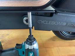
- Remove the Fender - Remove the 5 screws on the fender with a 3 mm Allen and place the fender on top of the battery (skip the step if no fender is installed).
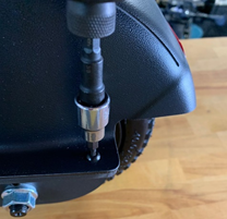
- Disconnect the Motor Connector - Cut any zip ties in the way with diagonal cutters in order to access the motor connector. Pull the cable up to gain access to the connector, twist the silver connector counterclockwise until it disengages with the threads, and then pull the connector apart. With the connector apart, pull the motor side of the cable out of the black RTV sealant.
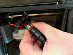
Models without the twist lock can be pulled apart. Older models with 3 single wires (yellow/green/blue) and a fourth 5 pin connector will need to have the shrink tube cut off with a utility knife or scissors before disconnecting.
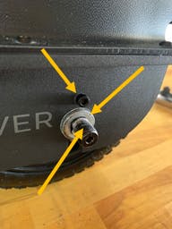
- Remove Motor Mounting Hardware - Remove the motor nut with an adjustable wrench or a socket (21, 19, or 18 mm depending on the model) as well as the motor screws (right above motor nut) on both sides of the motor shaft with a 4 mm Allen (older models may require a 3 mm Allen).
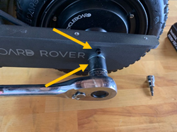
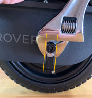
- Drop the Motor - Use an adjustable crescent wrench on the motor shaft to adjust the shaft until the flat sides of the shaft are parallel with the slot in the swingarm. Once aligned it should be easy to lift the rear of the board from the swing arm off the motor.
- Remove the Brake Disk - Remove the 6 screws on the brake disk with a 4 mm Allen and take the disk off (older models may require a 3 mm or a 5 mm Allen for the brake disk screws).
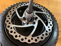
- Installing the Brake disk - Install the new brake disk in the same orientation as below and tighten the 6 screws a second time to ensure all screws are fully tightened.
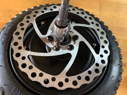
Try not to touch the surface of the disk by handling it by the edges to prevent contamination of the braking surface.
- Install the Motor Keepers - Install the motor keepers (pear-shaped black plates) all the way onto the shaft on each side and drop the swing arm of the scooter onto the motor. Make sure the motor keepers fit on the inside of the swingarm and the brake disk lines up inside the brake pads. The small hole in the keepers should face upward when the motor is installed.
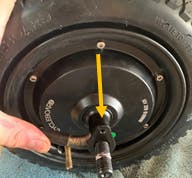
- Install Motor Mounting Hardware - Install the motor screw with a 4 mm Allen on each side of the motor, followed by the motor washer (bend side facing down and toward the motor), and finally install the motor nut and tighten an adjustable crescent wrench. Reinstall the fender after running the motor cable into the chassis.
- Motor Connector - Reconnect the motor connector by aligning the arrows or patterns on each side of the connector, pushing the connector firmly together, and then tightening the silver ring with (clockwise). After tightened, push the connector down into the floor of the controller compartment.
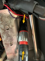
Single connectors without a twist-lock can simply be pushed together after aligning the 2 sides. With older models that have 4 connectors, ensure that the 3 single wire connects are covered with the green translucent covers.
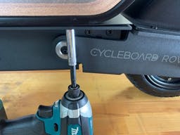
- Close the Deck - Press the cable down into the slot on the left side of the board where it enters the chassis, and close the deck making sure not to pinch any cables. Install the 4 locknuts under the left edge of the deck and tighten with an 8 mm socket.
Have more questions? Contact support@cycleboard.com


