Rear Tire/Tube Replacement (10" x 3.5")
Rover GEN2/Golf. Rear Tire & Inner Tube replacement for Rover GEN2 and Golf models 10" x 3.5"
Rear Tire/Inner Tube Replacement Video
Required Equipment
- 8 mm socket
- 3 mm Allen
- 4 mm Allen
- Adjustable Crescent Wrench
- Diagonal Cutters (or scissors)
- Rubber Mallet
- Bike Pump
Recommended Equipment
- 21 mm Socket
- Ratchet for 21 mm Socket
Procedures
- Open the Deck - Remove the 4 locknuts under the left edge of the deck and hinge open toward the right of the board.
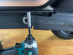
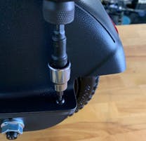
- Remove the Fender - Remove the 5 screws on the fender with a 3 mm Allen and place the fender on top of the battery.
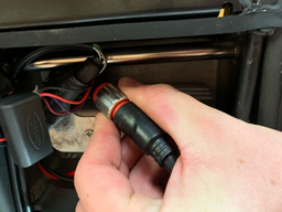
- Disconnect the Motor Connector - Cut any zip ties in the way with diagonal cutters in order to access the motor connector. Pull the cable up to gain access to the connector, twist the silver connector counterclockwise until it disengages with the threads, and then pull the connector apart. With the connector apart, pull the motor side of the cable out of the black RTV sealant.
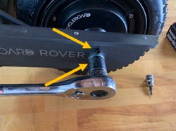
- Remove Motor Mounting Hardware - Remove the motor nut with an adjustable wrench or a 21 mm socket as well as the motor screws (right above the motor nut) on both sides of the motor shaft.
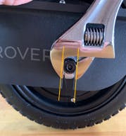
- Drop the Motor - Use an adjustable crescent wrench on the motor shaft to adjust the shaft until the flat sides of the shaft are parallel with the slot in the swingarm. Once aligned it should be easy to lift the rear of the board from the swing arm off the motor.
- Remove the Brake Disk - Remove the 6 screws on the brake disk with a 4 mm Allen and take the disk off.
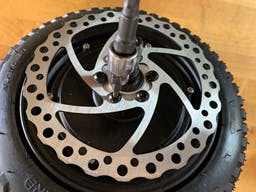
Try not to touch the surface of the disk by handling it by the edges to prevent contamination of the braking surface.
- Separating the Motor - Remove the 6 screws on the opposing side of the motor with a 3 mm Allen and screw back in two screws 180 degrees apart from approximately 3 revolutions on each screw. Use a rubber mallet along with the 3 mm Allen to tap on the screw screws lightly alternating between each screw.
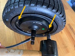
- Separating the Motor - Thread a motor nut onto the brake disk side of the motor 22.5and tap that motor nut against the ground (use a soft surface such as carpet) and hold the motor with two hands by the tire. The impact will force the rim apart.

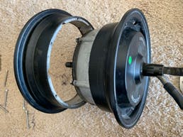
- Install the Inner Tube - Inflate the Inner Tube enough just to maintain a “donut” shape and install it into the tire with the valve facing upward and the arrow on the tire sidewall facing to the left when at the top of the tire.
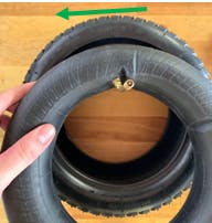
- Install the Tire - Install the tire onto the motor so that the valve passes through the hole on the motor (the side with the motor cable) making sure to rotate the tire with respect to the motor so that the valve is as straight as possible. Then slide the rim of the motor back on.
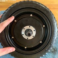
- Install Motor Screw - Install the 6 motor screws and tighten fully in a star pattern with a 3 mm Allen. After tightening all of the screws, tighten each screw once more. Pull the valve out of the motor, hold in position with a finger, and inflate the tire to 35 psi.
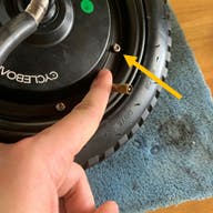
- Install the Brake Disk - Install the brake disk with a 4 mm Allen by tightening all of the screws fully in a star pattern and then tightening each screw again to ensure all screws are fully tightened.
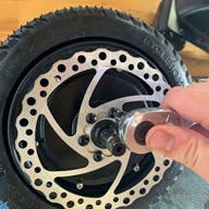
- Install the Motor Keepers - Install the motor keepers (pear-shaped black plates) all the way onto the shaft on each side and drop the swing arm of the scooter onto the motor. Make sure the motor keepers fit on the inside of the swingarm and the brake disk lines up inside the brake pads. The small hole in the keepers should face upward when the motor is installed.
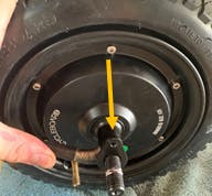
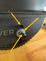
- Install Motor Mounting Hardware - Install the motor screw with a 4 mm Allen on each side of the motor, followed by the motor washer (bend side facing down and toward the motor), and finally install the motor nut and tighten with a 21 mm socket or an adjustable crescent. Reinstall the fender with the 5 fender screws with a 3 mm Allen.
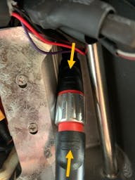
- Motor Connector - Reconnect the motor connector by aligning the 2 stripes on each side of the connector, pushing the connector firmly together, and then tightening the silver ring (clockwise). After tightening, push the connector down into the floor of the controller compartment.
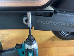
- Close the Deck - Press the cable down into the slot on the left side of the board where it exits the chassis, and close the deck making sure not to pinch any cables. Install the 4 locknuts under the left edge of the deck and tighten them with an 8 mm socket.
Have more questions? Contact support@cycleboard.com


